Variable stiffness composites (VSC) demonstrate enhanced mechanical properties compared to conventional carbon fiber reinforced plastics (CFRP).
In the design phase, finite element analysis (FEA) is used to optimize layup directions, which need to be transformed into viable tool paths for automated fiber placement (AFP) processes, where manufacturing defects such as wrinkles, gaps, and overlaps should be handled.
In this article, a novel path planning algorithm is discussed for variable steering in AFP. The fiber directions are clustered and for each cluster a reference curve is fitted as B-Spline, where manufacturing constraints are considered. Relevant case studies are also presented to validate the discussed tool path planning approach.
Light weighting is indispensable for sustainability in high value manufacturing. Since first commercial use in the 1960s1, CFRP has offered high strength-to-weight ratio, which makes CFRP materials great candidate for light weighting in aerospace, automotive, and marine.
In life cycle analysis of CFRP in automotive, by Duflou2 it was emphasized that CFRP leads to less energy consumption compared to metals, in intensive use for car body design. In CFRP manufacturing, laminates are convention ally laid up by hand, even for large parts such as aircraft wings, which requires significantly increased time, cost, and skillset. To address such issues, AFP technology with the tow concept was introduced in the 1970s, followed by implementation in commercial aerospace3.
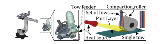
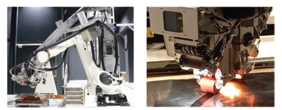
A gantry or a robotic system is retrofitted with a specially designed fiber placement head (see Figure 14) to lay a series of tows, which form courses to establish a ply, multiple of which create a layer of laminate.

Recently, it was shown that5 stress-oriented tool path planning in 3D printing leads to significant improvements in mechanical properties. A similar approach is also viable in AFP, where the direction and coverage of the part surface depend on the layup strategy.
This is relevant to the flexibility in design and manufacturing. Typical strategies are (i) constant angle, (ii) geodesic, and (iii) variable steering. Fixed angle steering involves the creation of a reference curve along a constant angle with respect to a desired direction on the part surface.
Geodesic steering is based on the shortest path between two points on the part surface along zero curvature. Variable angle steering is advantageous over these, as the layup can be aligned to the load direction in manufacture of variable stiffness composites.

In one of the early studies, Shirinzadeh et al.6 developed a feasible approach for constant angle path generation. In their approach, a reference curve is generated by projecting
a constant axis, which is then propagated at a marching distance based on the local surface curvature and tow width. Recently, design of VSC caught attention with an emphasis on optimizing the layup direction for light weighting, by introducing the fiber direction as a
new design variable.7 In variable steering, design complexity and the possibility of generating defects increase. Hence, conformance of the tool path to optimized layup
directions is crucial to achieve desired mechanical performance.(8)
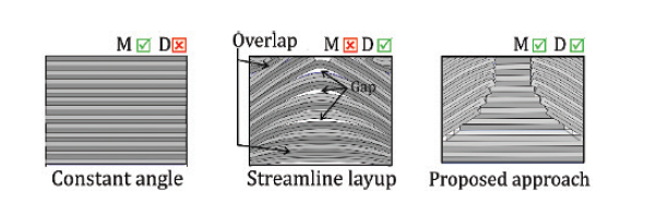
*M: Manufacturability, D: Design4
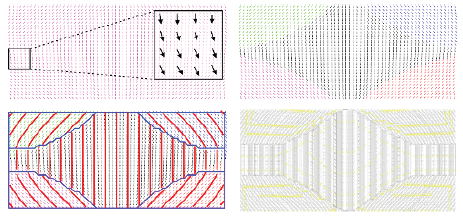
In this article, we discuss a novel FEA-integrated path generation approach for variable steering in AFP, where manufacturing constraints are enforced to control defects at the path planning phase. The anisotropic mechanical properties of CFRP materials are benefited to realize VSC, where the fibers are aligned with the load direction. This is contrary to the conventional AFP tool path generation, which uses constant direction lay-up and does not conform to the optimum, varying fiber directions obtained from FEA. Hence the part performance is suboptimal as variable steering is ignored (see Figure 4). It is possible to define several objective functions to optimize the mechanical structure of the part, such as but not limited to strain energy, buckling or natural frequency. In this article, optimization is performed based on 1st natural frequency just as a case study.
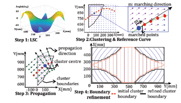
surface fitting (b) reference path
(c) parallel path propagation (d)boundary
refinement4.
Tool Path Planning for AFP
In FEA, fiber directions can be calculated according to several patterns: (i) constant angle, (ii) streamline, (iii) discretely variable angle, each of which compromises between design optimization and manufacturability. For instance, constant angle optimization (see Figure 4a4) has the highest manufacturability at the expense of reduced strength-to-weight ratio. Contrarily, streamline fiber alignment favors design optimization, but manufacturability
is challenging (see Figure 4b4). Thus, FEA-obtained fiber directions need to be processed by efficient tool path planning, which controls inter-tow distance to prevent manufacturing defects having adverse effects on mechanical performance. In this paper, cluster-based
tool path planning is proposed as illustrated in Figure 4c4 and as explained step-by-step in Figure 5.
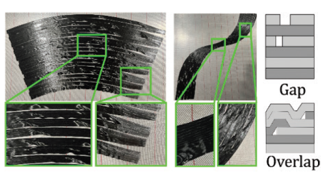
offset, (c) wrinkles and gaps, (d) wandering tow,
(e) overlaps, (f) waviness4.
Manufacturing Defects in AFP
In AFP, gap and overlap area percentage is used to rate the part performance as opposed to design. In the literature9, it is shown that gaps from 2% to 12% linearly reduces buckling and in-plane stiffness and the acceptable limit depends on the application. Surface coverage, head positioning, tow wandering, missing tows, layup speed, and compaction force are the sources for defects. In Figure 6a and Figure 6b, fiber courses of a ply laid according to parallel and shift offset methods are shown, respectively, where wrinkles, wandering tow, overlaps and waviness are observed.
Experimental Demonstration
The proposed approach is demonstrated on laying the 1st layer of a multi-layered, simply supported plate (1000mm x 500 mm), where the experimental validation is performed on the AFP system shown in Figure 8. The slit tapes are thermoset CFRP with 3000 fibers per bundle and weight of 150 g/m2, produced by KordSA©.
Tool Path Generation
As a representative case, fiber vector distribution is identified, as shown in Figure 7a, to increase the 1st natural frequency to 16 Hz, where the manufacturing radius constraint is 0.5 m. However, the natural frequency value is not verified in the context of the study. The reference curves and propagated paths for each cluster are shown in Figure 7c and Figure 7d, respectively. Radii of the propagated paths are limited at 0.5 m to prevent wrinkles due to lateral bending of tows. Finally, the path is exported to IGES file for kinematic simulation in commercial software CAD-Fiber©.
Verification and AFP Manufacturing
First, kinematic validation was performed on commercial AFP software, CAD-Fiber©, as compared with the actual product in Figure 9a and Figure 9b. The maximum gap was measured as 0.29 mm, which is less than ±0.50 mm given in the robot’s accuracy specification. However, defects due to process parameters, robot positioning, and velocity, cannot be identified in the software. Thus, layup trials were performed. The close-up views of critical areas are shown in Figure 9 and Figure 9c. The gap area percentage measurements were made by image processing (see Figure 9d). The complete laid layer is shown in Figure 9e.
AFP spools feed the tows at 80 mm from the roller. Therefore, when the tows are cut, the last 80 mm portion is not controlled. Consequently, the laid courses deviate from
the path, leading to gaps or overlaps up to 2 mm (see Figure9c), which is not attributed to the path. Thus, the model’s domain is extended by 80 mm as shown in Figure 9e, where
the trim boundary is shown as the white tape and to be later trimmed. The maximum gap is measured as 1.00 mm (see Figure 9c), which is around 16% of the 6.35mm tow width. The average gap area percentage is measured as 5%. Thus, it can be concluded that the proposed variable steering algorithm can lay decent plies. Visual inspection showed that layer is free of wrinkles and waviness.
Conclusions
This article, discusses a novel approach for tool path generation to achieve variable direction steered AFP in manufacture of VSC. Tool path computation is performed by using
fiber courses obtained from FEA, where manufacturing defects like gaps, overlaps and wrinkles are not considered yet. The fiber courses are clustered by normalized cut segmentation. 10 At each cluster, a reference curve is fitted through the fiber courses. Then, tow paths are generated by parallel propagation of the reference curve subject to
minimum layup length and maximum layup curvature. So that, manufacturability
and optimized fiber courses are considered as a significant advancement to the AFP process literature. As the study claims transforming the FEA obtained directions into manufacturable tool path, the verification of the proposed approach is performed through AFP layup trials.
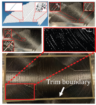
CAD-Fiber tool path and laid portion,
(b) measurement of manufacturing
gaps, (c) close view of critical areas, (d)
gap area percentage measurement by
image process, (e) complete view of the
laid ply4.
Acknowledgements
The authors gratefully acknowledge the support of TUBITAK under grant number 218M715 and support of KordSA for supplying the tow prepregs used in experimental demonstration.
References: 1Dorey G (1987) Carbon fibres and their applications. Journal of Physics D: Applied Physics, 20/3:245. 2Duflou JR, De Moor J, Verpoest I, Dewulf W (2009)
Environmental impact analysis of composite use in car manufacturing. CIRP Annals. 3Anderson RL, Grant CG (1991) Advanced fiber placement of composite fuselage structures. In NASA.
Langley Research Center, First NASA Advanced Composites Technology Conference, Part 2. 4 Tunc, L. T., & Sheikhi, M. (2023). AFP tool path planning for manufacture of variable stiffness
composites. CIRP Annals.5Li Y, Xu K, Liu X, Yang M, Gao J, Maropoulos P (2021) Stress-oriented 3D printing path optimization based on image processing algorithms for reinforced loadbearing
parts. CIRP Annals, 70(1), 195-198. 6Shirinzadeh B, Cassidy G, Oetomo D, Alici G, Ang Jr MH (2007) Trajectory generation for open-contoured structures in robotic fibre placement,
Robotics and Computer-Integrated Manufacturing, 23/4:380-394. 7Rasool M, Singha MK (2019) Stability of variable stiffness composite laminates under compressive and shearing follower
forces, Composite Structures, 225, 111003. 8Brooks TR, Martins JR (2018) On manufacturing constraints for tow-steered composite design optimization, Composite structures, 204:548-559.
9Nik MA, Fayazbakhsh K, Pasini D, Lessard L (2014). Optimization of variable stiffness composites with embedded defects induced by automated fiber placement. Composite Structures,
107:160-166. 10Shi J, Malik J (2000). Normalized cuts and image segmentation. IEEE Trans. on Pattern Analysis and Mach. Intelligence,22/8:888–905.
Assoc. Prof. Dr. L. Taner Tunç
Faculty of Engineering and Natural Sciences
Manufacturing Research Laboratory
Sabanci University